Home / Work / Cycloidal gearbox
Scaling up a cycloidal gearbox for a robot arm
Case study — supplied STL, modified and printed
A customer building a robot arm sent through the STL for a cycloidal gearbox and asked for a larger version of it. The housing and its front flange were modelled up to the new size, prototyped and test-fitted, and two complete sets were printed.
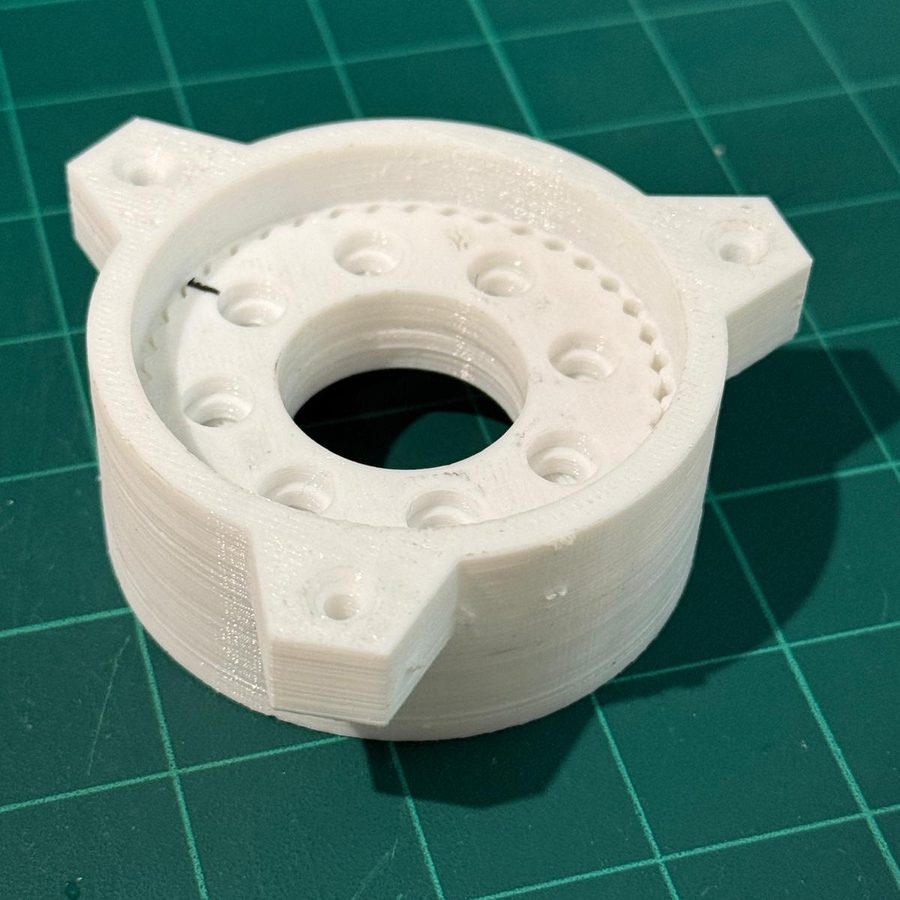
The job in short
- ARRIVED ASAn STL supplied by the customer
- THE ASKThe same gearbox, larger
- PRINTEDTwo complete sets
- PROCESSModel, prototype, test fit, adjust, print
Every detail on this page came from the job itself. Nothing here is inferred from the photograph.
What the customer wanted
The enquiry came from someone building a robot arm. They already had a cycloidal gearbox design and an STL file for it — what they did not have was that design at the size their arm actually needed. The ask was simple to state and less simple to do: make this gearbox bigger, and print me two full sets of it.
Cycloidal gearboxes suit printing better than most reduction drives. They multiply torque through an eccentric lobed disc rolling against a ring of pins rather than through fine meshing teeth, so most of the geometry is curved surfaces and bores rather than fine teeth — and curved surfaces and bores are what FDM printing handles well.
Why scaling an STL is not just scaling an STL
Typing a percentage into a slicer scales everything at once, and that is exactly the problem. A gearbox is not made only of the parts you print. It runs on bearings, it is held together with fasteners, and it turns on a shaft — and none of those come in arbitrary sizes. Scale a housing up and the bearing seat becomes a diameter no bearing is made in, the fixing holes stop matching any screw you can buy, and the shaft bore fits nothing on the shelf.
So the printed geometry grows and the hardware interfaces stay where they are. That means going back into the model and re-deriving every feature that has to mate with a real bought component, rather than letting the slicer stretch it along with everything else.
Measuring the front flange
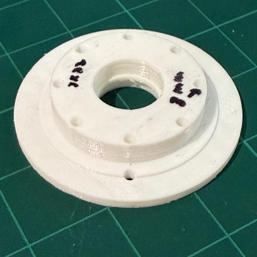
The second photograph on this page is the front flange of the same gearbox, and the pen marks on its face are the working. Features get measured, checked and ticked off directly on the part as they are captured, which is the quickest way to be certain nothing has been missed and nothing has been recorded twice. It is not a tidy process to look at. It is a reliable one.
What is on that flange is geometry other parts have to match — the central bore, the ring of fixings, the stepped profile. An error there does not stay local. It propagates through the assembly and shows up as parts that will not go together, after both sets have already been printed.
Prototype, fit, then commit
A prototype went on the printer before the full run did. That is the step that catches the difference between a model that looks right on screen and a part that goes together in your hands: whether the bore takes the bearing, whether the fixings line up, whether the fit is snug or sloppy. Adjustments were made against a part that existed, not against a guess, and only then were the two complete sets printed.
This is the same sequence used on every job here — measure, model, print one, fit it, adjust, then print the rest. It costs a print and a day. It is considerably cheaper than a set of parts that do not assemble.
What this job shows
Two things worth drawing out. The first is that a supplied file is a starting point, not a finished job. A good number of enquiries arrive as “just print this”, and a fair share of those files need real work before they will produce a part that functions. Saying so before printing is cheaper for everyone than saying so afterwards.
The second is that printing and modelling are not separate services with a wall between them. This job was both at once, and the modelling was where the value sat. If you have a file that is nearly right, or right at the wrong size, that is a normal job here rather than an awkward one.
Got a part like this one?
Send a photo of the part, drawing or assembly with a rough size, and tell us the machine or assembly it's for. Minimum order $75.
Email a photo for a quoteOther jobs from the workshop
A print-in-place planetary gear set for a university robotics project
A university robotics project sent an STL with no running clearance between the gear teeth. Adjusted, printed at 0.1 mm and tested twice before delivery.
Modelling a small centrifugal pump that someone else could print
A customer wanted a small centrifugal pump they could print themselves. Modelled from scratch and prototyped, with printability as a design constraint.